Solution
Furnace & Kiln Lining Solutions
A refractory lining is not one material. It is built in layers: a working layer against the process, a permanent layer behind it, an insulation layer behind that, and the steel shell outside. Each layer is supplied from a different product family, and the material in each changes with the equipment and the operating zone.
What the Solution Covers
RISING’s technical references describe a lining the same way whatever the equipment: as an ordered set of layers, each with its own job and its own material. The ironmaking technical reference tabulates them as the insulation layer, the permanent layer and the working layer. The power technical reference draws the same idea as a wall section reading refractory brick, insulating brick, fiber product and steel shell from the process outwards. The steel ladle diagrams use insulation lining and permanent lining for the same positions, and the glass technical reference calls the layer behind the working face a safety layer.
What changes between industries is not the structure but the material in each layer, and the technical references are specific about that. A gasifier working face is high chrome brick; a converter impact area is magnesia carbon brick; a CFB separator target area is a steel-fiber-reinforced wear-resistant castable. Those assignments belong to the equipment and are published on the industry pages, each one tied to the equipment and zone it applies to.
This page does not repeat them. It explains the layer principle, names the product families that supply each layer, and points to the industry page where the equipment you are working on is mapped zone by zone. Material and grade for a specific furnace are confirmed against your operating conditions when the enquiry is reviewed.
Working layer
The layer in contact with the process. The technical references assign it by zone rather than by vessel: a converter slag line, a blast furnace hearth and a glass melting tank each take a different material, and the same vessel changes material between zones.
Permanent layer
The layer behind the working face. The iron source calls it the permanent layer and the steel ladle diagrams call it the permanent lining; the glass source calls the equivalent position a safety layer.
Insulation layer
The layer that controls heat loss and protects the shell. Supplied as insulating brick, lightweight castable or ceramic fiber depending on the position.
Steel shell
The outer structure the lining is built against. The power source shows the fiber product placed directly against it, and monolithic linings anchored back to it.
Lining System
Refractory Materials Involved
Refractory Bricks
31Shaped refractory products for steel, cement, glass, nonferrous, power and industrial furnace applications, in multiple material systems and custom shapes.
Monolithic Refractories
17Castables, ramming materials, mortars and other unshaped refractory systems for new linings, maintenance and repair.
Thermal Insulation Materials
4Insulating bricks, boards and lightweight refractory systems designed to reduce heat loss and support multilayer lining construction.
Ceramic Fiber Products
3Lightweight high-temperature fiber products for furnace insulation, lining, sealing and thermal management.
Silicon Carbide Products
5Silicon carbide refractory materials and engineered components for demanding wear, corrosion and high-temperature service.
Steelmaking Refractory Products
4Functional refractory products for steel casting and flow control: sliding plates, ladle shrouds, monoblock stoppers and submerged entry nozzles.
Industries Supported
Steel & Iron
View refractory selection by equipmentPower & CFB Boilers
View refractory selection by equipmentNonferrous Metals
View refractory selection by equipmentGlass
View refractory selection by equipmentChemical & Petrochemical
View refractory selection by equipmentCement
View refractory selection by equipment
Technical Considerations
- One vessel does not take one material
- Every lining diagram in RISING’s technical references assigns different materials to different zones of the same vessel. The converter, electric furnace and ladle diagrams each name an impact or hot-spot area, a slag line, a working lining and a permanent lining with a different grade against each.
- Shaped and unshaped are specified together
- The technical references list shaped refractories and unshaped refractories separately for each piece of equipment, so a lining specification normally names both bricks and monolithics for the same vessel.
- Monolithic linings are anchored
- The power source's construction detail for special parts shows the wear-resistant castable and the lightweight insulating layer carried on anchors back to the steel shell, with a needled blanket against the shell itself.
- Layer order is read from the process side
- The power source's separator wall drawing reads refractory brick, insulating brick, fiber product, steel shell from the inside out. The petrochemical gasifier legends read the same way: working face first, shell last.
Related Products
Materials from the families this service covers that the published selection tables specify, most frequently specified first.
Refractory Bricks
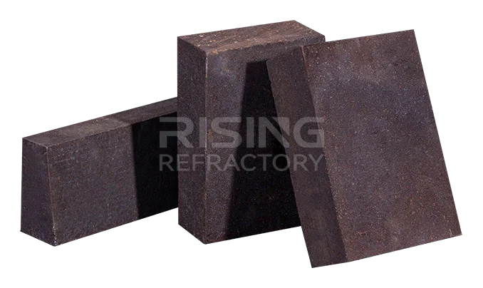
Magnesia Chrome Brick
Basic magnesia–chrome bricks in four product types: ordinary, direct-bonded, fused semi-rebonded and fused rebonded, covering 23 grades for demanding basic-slag service.
View ProductGradesMG-16A · MG-16B · MG-12A · MG-12B · MG-8A · MG-8B · ZMG-16A · ZMG-12A · ZMG-8A · ZMG-6 · BMG-26 · BMG-24 · BMG-22 · BMG-20A · BMG-18 · BMG-16A · BMG-12A · DMG-26 · DMG-24 · DMG-22 · DMG-20 · DMG-16 · DMG-12
Monolithic Refractories
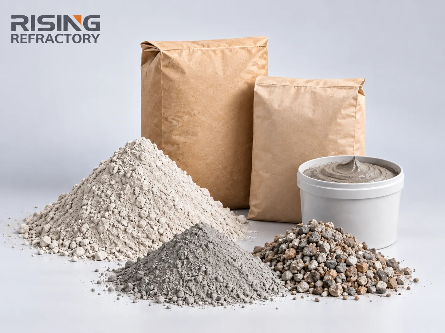
Lightweight Insulation Castable
Low-density insulating castable with low thermal conductivity, excellent thermal insulation and convenient installation, reducing furnace heat loss and lining weight. Grades LW0.6 to LW1.3.
View ProductGradesLW0.6 · LW0.8 · LW1.0 · LW1.1 · LW1.3
Monolithic Refractories
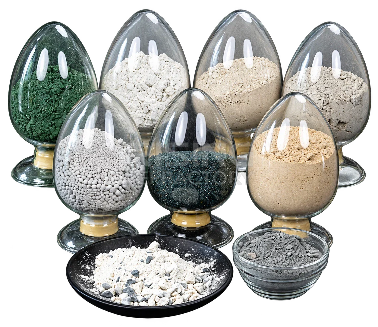
Low & Ultra-Low Cement Castable
Dense low- and ultra-low-cement castables in clay, high alumina and corundum materials, with small pore size, high density, good volume stability, high strength and low water addition.
View ProductGradesClay · High Alumina · Corundum
Silicon Carbide Products
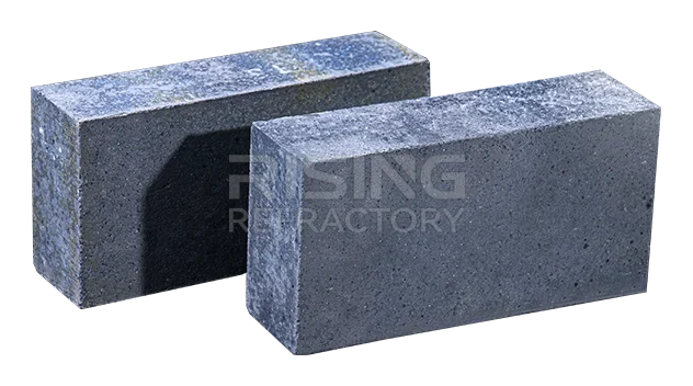
Silicon Carbide Brick
Non-oxide silicon carbide brick with high wear and corrosion resistance, high hot strength, high thermal conductivity and low thermal expansion, in six bonding types from SiO₂-bonded to recrystallized.
View ProductGradesSiO₂ · Clay · Si₃N₄ · Sialon · Self Bonded · Recrystallized
Refractory Bricks
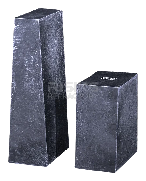
Magnesia Carbon Brick
Carbon-bonded magnesia brick combining the slag resistance of magnesia with the thermal conductivity and low expansion of carbon, in grades MT10A to MT18A by carbon content.
View ProductGradesMT10A · MT12A · MT14A · MT16A · MT18A
Monolithic Refractories
Refractory Mortar
Refractory mortars for brick masonry in four material systems: silica, alumina-silicate, alkaline (magnesia) and silicon carbide / carbon, each with its own grades and specification table.
View ProductGradesGNR94 · GNJ94 · GNB94 · GNB96 · LN65 · LN75 · LN65P · LN75P · GN85P · GN90P · MN91 · MN95 · MN97 · MLN70 · MLN80 · SCN · TN-1 · TN-2 · TN-3
Refractory Bricks
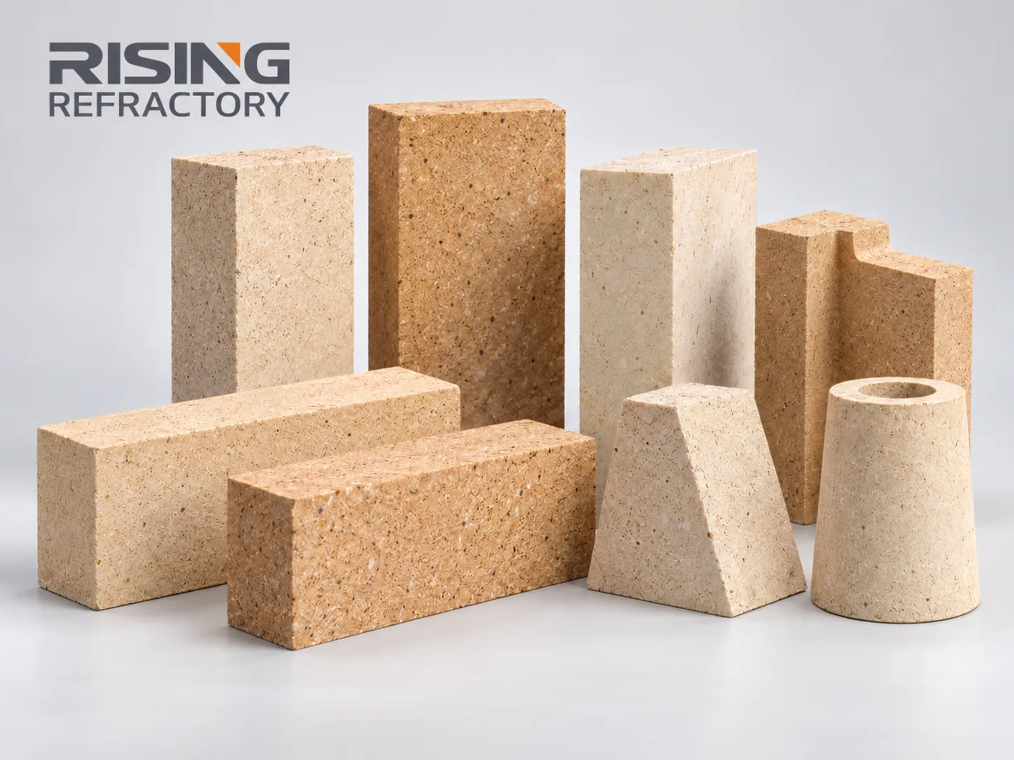
Alkali-Resistant Brick
Alkali-resistant brick with high strength and good volume stability that forms a high-viscosity glass phase on contact with alkali to block alkaline slag, in ordinary, high-strength, arch and lightweight types.
View ProductGradesPT · HS · DT · LW
Refractory Bricks
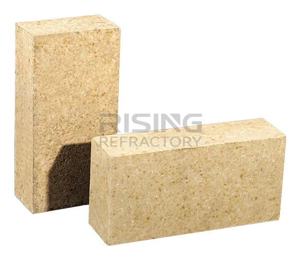
High Alumina Brick
Neutral alumina–silica refractory brick with resistance to both acidic and alkaline slag, high cold crushing strength and high refractoriness under load. Six grades from LZ-48 to LZ-80.
View ProductGradesLZ-80 · LZ-75 · LZ-70 · LZ-65 · LZ-55 · LZ-48
Refractory Bricks
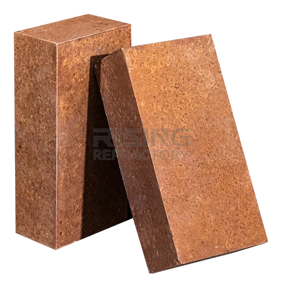
Magnesia Brick
Basic refractory brick with strong resistance to alkaline slag, high refractoriness and high refractoriness under load, in seven grades from M89 to M98.
View ProductGradesM98 · M97A · M97B · M95A · M95B · M91 · M89
Monolithic Refractories
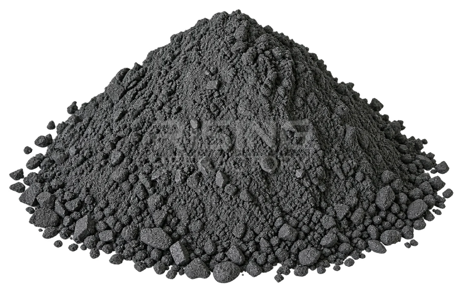
Al₂O₃-SiC-C Castable
Alumina–silicon carbide–carbon castable for iron and slag runners, with strong resistance to molten iron and slag, good thermal shock and oxidation resistance, and fast bake-out without bursting.
View ProductGradesSlag Line of Main Iron Runner · Iron Line of Main Iron Runner · Branch Iron Runner · Slag Runner
Ceramic Fiber Products
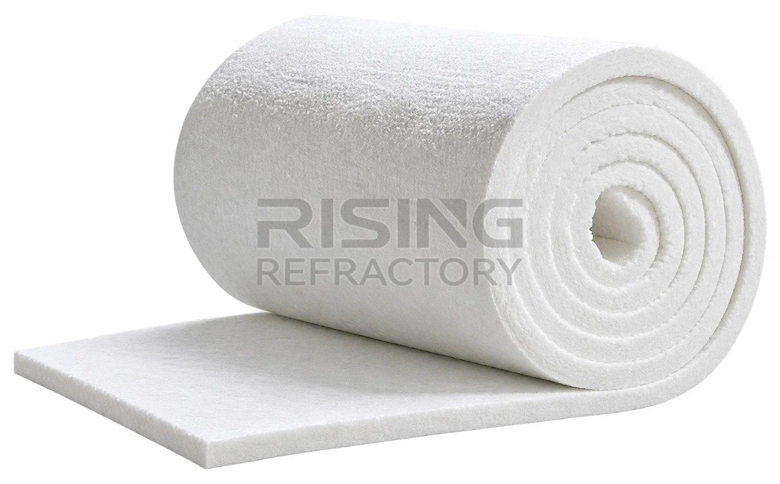
Ceramic Fiber Blanket
Ceramic fiber blanket combining fire resistance, heat insulation and heat retention, with low heat capacity and thermal conductivity, in standard, high-purity, high-alumina and zirconia-containing grades.
View ProductGradesSTD · HP · HA · HZ
Ceramic Fiber Products
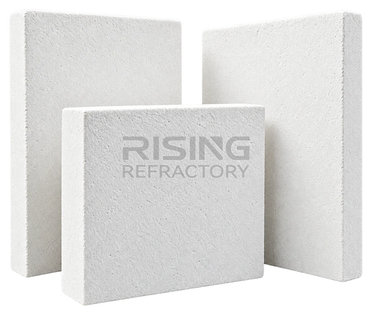
Ceramic Fiber Board
Rigid ceramic fiber board with excellent toughness, strength and wind-erosion resistance, light and easy to cut, for kilns, pipes and other thermal insulation equipment. Standard, high-purity, high-alumina and zirconia grades.
View ProductGradesSTD · HP · HA · HZ
Reference documents
This page is prepared from RISING company records, product documentation and technical references.
Technical Consultation
Tell us your equipment, process and operating conditions
Our team reviews the requirement and helps identify the appropriate refractory materials. Service conditions are reviewed before any material is proposed.