
Carbon / Graphite ProductsGraphite electrodes
Graphite Electrode
RISING graphite electrodes are supplied in RP, HP and UHP grades for electric-arc furnace service, with the physical properties, allowable current, standard dimensions and tolerances given in the specifications below.
- Grades / types
- RP, HP, UHP
- Nominal diameters
- 75–700 mm (3"–28")
- Standard lengths
- 1600–3000 mm by diameter
Product overview
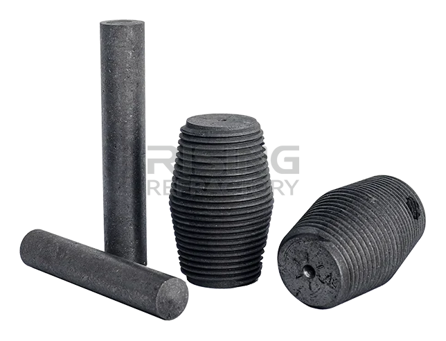
Graphite electrodes are supplied in the three standard classes RP (regular power), HP (high power) and UHP (ultra-high power), in nominal diameters from 75 mm to 700 mm. Each class is specified for the electrode body and for the matching nipple by nominal-diameter group: electrical resistivity, bending strength, elastic modulus, bulk density, coefficient of thermal expansion and ash content. Allowable current and current density are given per nominal diameter for each class, and standard diameters, lengths and tolerances are listed in the sizes table. Electrodes are joined with graphite electrode nipples, listed as a separate product.
Handling and use
Guidance for the storage, connection and operation of graphite electrodes, in RISING wording:
- Keep electrodes away from moisture, dust, dirt and impact, in use and in storage.
- Move electrodes by forklift with care: keep the load balanced, and never knock or overload them.
- Store in a clean, dry place; cover with tarpaulins when stored in the open.
- Before connecting, blow the electrode thread clean with compressed air, then screw the nipple carefully into one end and the lifting plug into the other, without letting the thread strike anything.
- Lift with a rotatable hook and put a soft support pad under the nipple end so the thread is not damaged.
- Blow the socket clean with compressed air before joining electrodes.
- Use an elastic hoist hook to lift the electrode onto the furnace, centre it, and lower it slowly.
- When the upper electrode is 20–30 mm above the lower one, blow the joint clean with compressed air.
- Tighten with a dedicated torque wrench to the specified torque, whether by mechanical, hydraulic or pneumatic means (see the reference torque table on the nipple page).
- Clamp the holder between the two white warning lines, keep the contact surface between holder and electrode clean, and do not let holder cooling water leak.
- Cover the top of the electrode to limit oxidation and dust build-up.
- Do not charge insulating blocks into the furnace, and keep the working current within the allowable current given above.
- Charge large material in the lower part of the furnace and small pieces on top, to reduce electrode breakage.
Technical data
| Property | Unit | 75–300 mm · YB | 75–300 mm · FC | 350–450 mm · YB | 350–450 mm · FC | 500–700 mm · YB | 500–700 mm · FC |
|---|---|---|---|---|---|---|---|
| Resistivity (max.) — Electrode | μΩ·m | 10.0 | 8.0 | 10.5 | 8.0 | 10.5 | 8.0 |
| Resistivity (max.) — Nipple | μΩ·m | 8.0 | 5.5 | 8.0 | 5.5 | 8.0 | 5.5 |
| Bending Strength (min.) — Electrode | MPa | 8.0 | 8.4 | 7.0 | 7.5 | 6.5 | 7.0 |
| Bending Strength (min.) — Nipple | MPa | 15.0 | 16.0 | 15.0 | 16.0 | 15.0 | 16.0 |
| Elastic Modulus (max.) — Electrode | GPa | 9.3 | 8.0 | 9.3 | 8.0 | 9.3 | 8.0 |
| Elastic Modulus (max.) — Nipple | GPa | 14.0 | 12.0 | 14.0 | 12.0 | 14.0 | 12.0 |
| Bulk Density (min.) — Electrode | g/cm³ | 1.53 | 1.60 | 1.53 | 1.60 | 1.52 | 1.60 |
| Bulk Density (min.) — Nipple | g/cm³ | 1.70 | 1.75 | 1.70 | 1.75 | 1.70 | 1.75 |
| C.T.E, room temp.–600 ℃ (max.) — Electrode | ×10⁻⁶/℃ | 2.9 | 2.8 | 2.9 | 2.8 | 2.9 | 2.8 |
| C.T.E, room temp.–600 ℃ (max.) — Nipple | ×10⁻⁶/℃ | 2.8 | 2.7 | 2.8 | 2.7 | 2.8 | 2.7 |
| Ash (max.) — Electrode | % | 0.5 | 0.3 | 0.5 | 0.3 | 0.5 | 0.3 |
| Ash (max.) — Nipple | % | 0.5 | 0.2 | 0.5 | 0.2 | 0.5 | 0.3 |
- Columns: nominal diameter group; YB = industry-standard value, FC = internal-control value, as labelled in the specification (行业 YB / 内控 FC).
- The specification marks resistivity, elastic modulus, C.T.E and ash as maxima (≤) and bending strength and bulk density as minima (≥) in the row labels; the values are reproduced as printed, without signs.
- Units are printed "Mpa", "Gpa", "g/cm3" and "×10-6/℃" in the specification; rendered here in the site's typographic form, values unchanged.
| Property | Inch | Allowable current (A) | Current density |
|---|---|---|---|
| 75 mm | 3" | 1000-1400 | 22-31 |
| 100 mm | 4" | 1500-2400 | 19-30 |
| 130 mm | 5" | 2200-3400 | 17-26 |
| 150 mm | 6" | 3000-4500 | 16-25 |
| 200 mm | 8" | 5000-6900 | 15-21 |
| 250 mm | 10" | 7000-10000 | 14-20 |
| 300 mm | 12" | 10000-13000 | 14-18 |
| 350 mm | 14" | 13500-18000 | 14-18 |
| 400 mm | 16" | 18000-23500 | 14-18 |
| 450 mm | 18" | 22000-27000 | 13-17 |
| 500 mm | 20" | 25000-32000 | 13-16 |
| 550 mm | 22" | 28000-34000 | 12-14 |
| 600 mm | 24" | 30000-36000 | 11-13 |
| 650 mm | 26" | 32000-39000 | 10-12 |
| 700 mm | 28" | 34000-42000 | 9-11 |
- Source heading reads "Allowable capacitance flow of the electrode"; the table gives allowable current in amperes and is labelled accordingly here. Values unchanged.
- The specification gives no unit for current density; the values are reproduced as printed.
| Property | Unit | 300–400 mm · YB | 300–400 mm · FC | 450–500 mm · YB | 450–500 mm · FC | 550–700 mm · YB | 550–700 mm · FC |
|---|---|---|---|---|---|---|---|
| Resistivity (max.) — Electrode | μΩ·m | 7.0 | 6.2 | 7.5 | 6.2 | 7.5 | 6.2 |
| Resistivity (max.) — Nipple | μΩ·m | 6.3 | 4.3 | 6.3 | 4.3 | 6.3 | 4.3 |
| Bending Strength (min.) — Electrode | MPa | 10.5 | 11.0 | 10.0 | 10.5 | 8.5 | 9.0 |
| Bending Strength (min.) — Nipple | MPa | 17.0 | 18.0 | 17.0 | 18.0 | 17.0 | 18.0 |
| Elastic Modulus (max.) — Electrode | GPa | 14.0 | 9.0 | 14.0 | 9.0 | 14.0 | 9.0 |
| Elastic Modulus (max.) — Nipple | GPa | 16.0 | 13.0 | 16.0 | 13.0 | 16.0 | 13.0 |
| Bulk Density (min.) — Electrode | g/cm³ | 1.60 | 1.67 | 1.60 | 1.67 | 1.60 | 1.67 |
| Bulk Density (min.) — Nipple | g/cm³ | 1.72 | 1.77 | 1.72 | 1.77 | 1.72 | 1.77 |
| C.T.E, room temp.–600 ℃ (max.) — Electrode | ×10⁻⁶/℃ | 2.4 | 2.0 | 2.4 | 2.0 | 2.4 | 2.0 |
| C.T.E, room temp.–600 ℃ (max.) — Nipple | ×10⁻⁶/℃ | 2.2 | 1.8 | 2.2 | 1.8 | 2.2 | 1.8 |
| Ash (max.) — Electrode | % | 0.5 | 0.3 | 0.5 | 0.3 | 0.5 | 0.3 |
| Ash (max.) — Nipple | % | 0.5 | 0.2 | 0.5 | 0.2 | 0.5 | 0.3 |
- Columns: nominal diameter group; YB = industry-standard value, FC = internal-control value, as labelled in the specification (行业 YB / 内控 FC).
- The specification marks resistivity, elastic modulus, C.T.E and ash as maxima (≤) and bending strength and bulk density as minima (≥) in the row labels; the values are reproduced as printed, without signs.
- Units are printed "Mpa", "Gpa", "g/cm3" and "×10-6/℃" in the specification; rendered here in the site's typographic form, values unchanged.
| Property | Inch | Allowable current (A) | Current density |
|---|---|---|---|
| 300 mm | 12" | 13000-17400 | 17-24 |
| 350 mm | 14" | 17400-24000 | 17-24 |
| 400 mm | 16" | 21000-31000 | 16-24 |
| 450 mm | 18" | 25000-40000 | 15-24 |
| 500 mm | 20" | 30000-48000 | 15-24 |
| 550 mm | 22" | 34000-53000 | 14-22 |
| 600 mm | 24" | 38000-58000 | 13-21 |
| 650 mm | 26" | 41000-65000 | 12-20 |
| 700 mm | 28" | 45000-72000 | 12-19 |
- Source heading reads "Allowable capacitance flow of the electrode"; the table gives allowable current in amperes and is labelled accordingly here. Values unchanged.
- The specification gives no unit for current density; the values are reproduced as printed.
| Property | Unit | 300–400 mm · YB | 300–400 mm · FC | 450–500 mm · YB | 450–500 mm · FC | 550–650 mm · YB | 550–650 mm · FC |
|---|---|---|---|---|---|---|---|
| Resistivity (max.) — Electrode | μΩ·m | 6.2 | 5.5 | 6.3 | 5.5 | 6.0 | 5.5 |
| Resistivity (max.) — Nipple | μΩ·m | 5.3 | 3.8 | 5.3 | 3.8 | 4.5 | 3.8 |
| Bending Strength (min.) — Electrode | MPa | 10.5 | 12.0 | 10.5 | 12.0 | 10.0 | 12.0 |
| Bending Strength (min.) — Nipple | MPa | 20.0 | 22.0 | 20.0 | 22.0 | 22.0 | 24.0 |
| Elastic Modulus (max.) — Electrode | GPa | 14.0 | 8.0 | 14.0 | 8.0 | 14.0 | 8.0 |
| Elastic Modulus (max.) — Nipple | GPa | 20.0 | 17.0 | 20.0 | 17.0 | 22.0 | 17.0 |
| Bulk Density (min.) — Electrode | g/cm³ | 1.67 | 1.69 | 1.66 | 1.69 | 1.66 | 1.69 |
| Bulk Density (min.) — Nipple | g/cm³ | 1.74 | 1.80 | 1.75 | 1.80 | 1.78 | 1.80 |
| C.T.E, room temp.–600 ℃ (max.) — Electrode | ×10⁻⁶/℃ | 1.5 | 1.4 | 1.5 | 1.4 | 1.5 | 1.4 |
| C.T.E, room temp.–600 ℃ (max.) — Nipple | ×10⁻⁶/℃ | 1.4 | 1.2 | 1.4 | 1.2 | 1.3 | 1.2 |
| Ash (max.) — Electrode | % | 0.5 | 0.3 | 0.5 | 0.3 | 0.5 | 0.3 |
| Ash (max.) — Nipple | % | 0.5 | 0.2 | 0.5 | 0.2 | 0.5 | 0.3 |
- Columns: nominal diameter group; YB = industry-standard value, FC = internal-control value, as labelled in the specification (行业 YB / 内控 FC).
- The specification marks resistivity, elastic modulus, C.T.E and ash as maxima (≤) and bending strength and bulk density as minima (≥) in the row labels; the values are reproduced as printed, without signs.
- Units are printed "Mpa", "Gpa", "g/cm3" and "×10-6/℃" in the specification; rendered here in the site's typographic form, values unchanged.
- In the specification the "Electrode" row label of the UHP resistivity row is blank; the values are in the electrode position and are transcribed as such.
| Property | Inch | Allowable current (A) | Current density |
|---|---|---|---|
| 300 mm | 12" | 15000-22000 | 20-30 |
| 350 mm | 14" | 20000-30000 | 20-30 |
| 400 mm | 16" | 25000-40000 | 19-30 |
| 450 mm | 18" | 32000-45000 | 19-27 |
| 500 mm | 20" | 38000-55000 | 18-27 |
| 550 mm | 22" | 45000-65000 | 18-27 |
| 600 mm | 24" | 50000-75000 | 18-26 |
| 650 mm | 26" | 60000-85000 | 18-25 |
| 700 mm | 28" | 70000-120000 | 18-30 |
- Source heading reads "Allowable capacitance flow of the electrode"; the table gives allowable current in amperes and is labelled accordingly here. Values unchanged.
- The specification gives no unit for current density; the values are reproduced as printed.
| Property | Inch | Actual diameter max. (mm) | Actual diameter min. (mm) | Rough spot min. B (mm) | Length (mm) | Length tolerance (mm) | Short length tolerance (mm) |
|---|---|---|---|---|---|---|---|
| 200 mm | 8" | 205 | 200 | 197 | 1600/1800 | ±100 | -275 |
| 250 mm | 10" | 256 | 251 | 248 | 1600/1800/2000 | ±100 | -275 |
| 300 mm | 12" | 307 | 302 | 299 | 1600/1800/2000/2200 | ±100 | -275 |
| 350 mm | 14" | 357 | 352 | 349 | 1600/1800/2000/2200 | ±100 | -275 |
| 400 mm | 16" | 409 | 403 | 400 | 1600/1800/2000/2200 | ±100 | -275 |
| 450 mm | 18" | 460 | 454 | 451 | 1600/1800/2000/2200 | ±100 | -275 |
| 500 mm | 20" | 511 | 505 | 502 | 1800/2000/2200/2400 | ±100 | -275 |
| 550 mm | 22" | 562 | 556 | 553 | 1800/2000/2200/2400/2700 | ±100 | -275 |
| 600 mm | 24" | 613 | 607 | 604 | 2000/2200/2400/2700/3000 | ±100 | -275 |
| 650 mm | 26" | 663 | 659 | 656 | 2000/2200/2400/2700/3000 | ±100 | -275 |
| 700 mm | 28" | 714 | 710 | 707 | 2000/2200/2400/2700/3000 | ±100 | -275 |
- Length tolerance ±100 and short-length tolerance −275 are stated once in the specification for all sizes and are repeated per row.
- "Rough spot (B)" is the specification's label for the minimum diameter of the black (unmachined) portion.
Available grades, shapes and sizes
Available grades
- RP
- HP
- UHP
Technical Consultation
Discuss your requirement with our technical team
Share your application, service conditions and quantities. Our engineers confirm the suitable grade and return a structured quotation.
Request a quote for prices and lead times, a TDS for the grade’s data sheet, or technical information for a selection or specification question.
Technical data sheets are supplied on request with the quotation.Request TDS